Sheet 09 · Resources · Rev A, October 2026
Startup and operation guide
Heat cable termination, panel wiring, zone-by-zone startup, touch screen operation and alarms for the freezer floor control panel.
This guide covers installation of the heating cable and sensors, system startup, and day-to-day operation of the Freezer Floor Systems control panel and touch screen. The number of zones, circuits, GFIs and breakers shown on the screens depends on the job; screens here show a typical system.
01Installation
Heating cable
- Install the heating cable in 3/4" rigid conduit (minimum) in the floor, as shown on the layout drawing.
- Pull each cable to a weatherproof junction box for both the power connection and the end-of-run connection.
- Terminate each cable end with the termination kit provided, following the steps below.
- Seal conduit ends with silicone caulk to keep moisture and warm air out of the junction boxes.
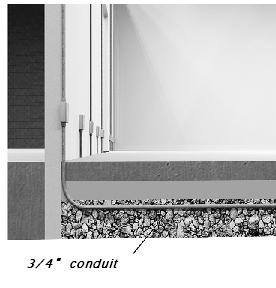
Terminating the heating cable
Each power end and end-of-run end of the heating cable is prepared the same way. Work in a clean, dry location and follow the steps exactly.
Steps 1–4: Remove the jackets and form the braid pigtail
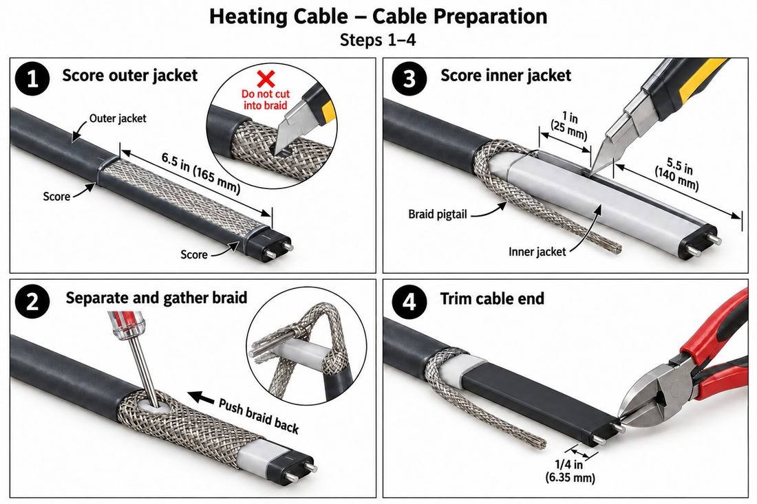
- Score the outer jacket 6.5 in (165 mm) from the end, then score lengthwise and remove it. Do not cut into the braid.
- Separate and gather the braid. Push the braid back, open it with a small screwdriver, work the cable out through the opening, and twist the braid into a pigtail.
- Score the inner jacket, leaving 1 in (25 mm) of inner jacket past the braid, and remove the remaining 5.5 in (140 mm). Do not nick the bus wires.
- Trim the cable end square, removing 1/4 in (6 mm).
Steps 5–8: Strip the core and lay out the parts
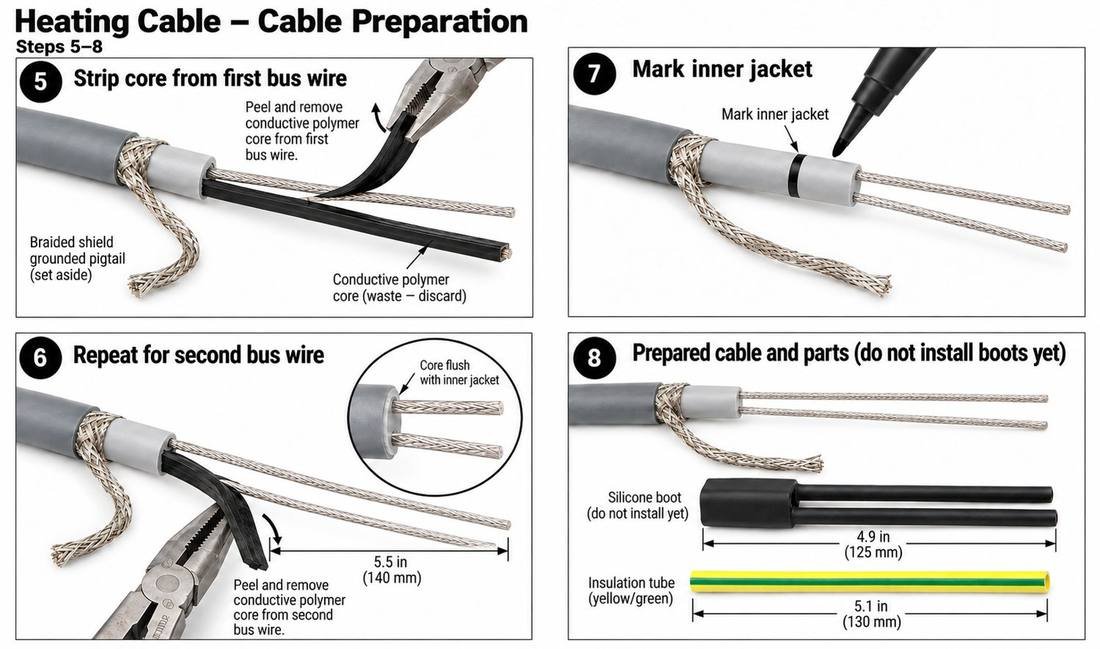
- Strip the core from the first bus wire. Peel the black conductive polymer away with pliers and discard it. Set the braid pigtail aside.
- Repeat for the second bus wire. Remove the core flush with the inner jacket; the bare bus wires should be about 5.5 in (140 mm) long. No black core material may remain on the wires.
- Mark the inner jacket as a reference for positioning the boot.
- Lay out the parts: silicone boot (4.9 in / 125 mm) and yellow/green insulation tube (5.1 in / 130 mm). Do not install the boot yet.
Steps 9–12: Seal the end and install the boot
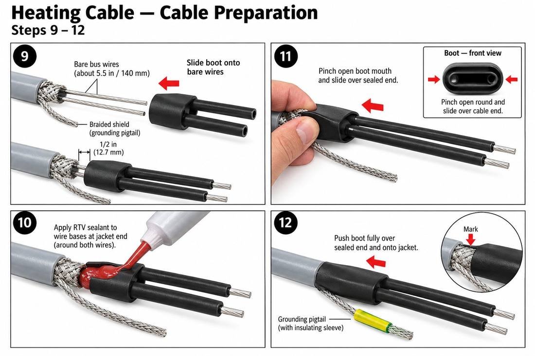
- Slide the boot onto the bare bus wires, stopping about 1/2 in (12.7 mm) from the jacket. Bus wires must not touch or cross.
- Apply RTV silicone sealant around the base of both wires at the jacket end.
- Pinch open the boot mouth and slide it over the sealed end.
- Push the boot fully over the sealed end and onto the jacket, up to the mark. Slide the yellow/green insulation tube over the braid pigtail – it is the ground connection.
Power connections
Size power wiring for the circuit load and terminate each heating circuit directly at its GFI (ground fault) breaker in the control panel, per the wiring diagram.
End-of-run monitor connections
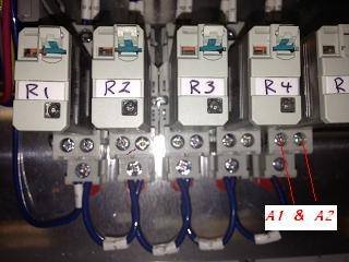
Each cable run has an end-of-run monitor. Wire the far end of each run back to its monitor relay (R1, R2 …) at terminals A1 and A2. This wiring carries less than 1 amp; size it accordingly.
Thermocouples
- Install each floor sensor in its own sensor conduit in the slab. Seal the conduit end before the slab is poured.
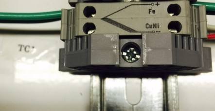
- Use Type J thermocouple extension-grade wire run directly to the control panel with no splices. For long runs, use shielded Type J extension wire.
- Land the leads on the terminals marked TC+ (Fe) and TC– (CuNi). On Type J wire the white lead is positive (+) and the red lead is negative (–). Reversed leads read incorrectly.
- If a zone has more than one sensor, the controller displays and controls from the lowest reading.
Remote alarm signal
The panel provides a 24 VDC alarm signal for a building or DCS system. Terminal numbers are shown on the wiring diagram for your panel. A relay for a dry contact can be supplied on request.
Peak demand setback (optional)
For peak-demand or utility load-shed programs, connect a normally open (N.O.) dry contact from the building management or utility demand system to terminals 3 and 5.
| Contact | Panel operation |
|---|---|
| Open (normal) | Each zone runs at its normal settings – Setpoint 55.0 °F, Deviation Alarm 10.0 °F. |
| Closed (peak setback) | All zones change to Setpoint 35.0 °F and Deviation Alarm 2.0 °F. Heating is held to the minimum needed to keep the slab above freezing. |
- During setback the low-temperature alarm stays active at 33 °F (35.0 – 2.0). If the floor falls toward freezing for any reason, the alarm sounds.
- When the contact opens, the zones return to their normal settings.
- Use a dry (unpowered) contact only. Do not apply voltage to terminals 3 and 5. Leave them open if peak setback is not used.
02Startup procedure
Record all readings on the Freezer Floor Startup Checklist.
Before power is applied
- Confirm cable terminations, junction box covers and conduit seals are complete, and the silicone has cured (24 hours).
- Confirm thermocouple leads are landed on the correct zone inputs with correct polarity.
- Check panel terminations for tightness and confirm the supply voltage at the main.
- Megger each heating circuit and record the reading. Use the test voltage and minimum value from the cable manufacturer's instructions.
With power on
- Turn on the main and each GFI breaker. The Main screen should show every zone's floor temperature.
- On the Temperature Setpoint screen, set every zone's setpoint below the current floor temperature so no zone is calling for heat.
Check out one zone at a time
Test the zones one at a time. With only one zone heating, you can confirm that each end-of-run monitor relay is wired to the correct zone. Repeat for each zone:
- Raise this zone's setpoint above the current floor temperature. Confirm only this zone shows Heat On.
- At the monitor relays, confirm that only the relays for this zone are energized, and record the voltage at A1/A2 of each. If a relay for another zone energizes, or one of this zone's relays does not, the end-of-run wiring is crossed or open – correct it before continuing.
- Open one end-of-run connection in this zone and confirm a continuity alarm on the correct relay (r#) on the Circuit Monitor Fault screen. Reconnect it.
- Press the test button on this zone's GFI breaker and confirm the GFI alarm shows the correct GFI. Reset it.
- Turn off this zone's circuit breaker and confirm the CB alarm shows the correct breaker. Turn it back on.
- Force a temperature alarm: raise this zone's setpoint more than 10 °F above the current floor temperature. After the 5-second delay, confirm the zone turns red and the TEMP ALARM button appears.
- On the first zone, press Silence during an alarm and confirm the horn stops, the stack light comes on, and the remote alarm signal stays on while the fault exists. Clear the fault and confirm the system returns to normal by itself.
- Set this zone's setpoint back below the actual floor temperature so it stops heating, then move to the next zone.
All zones – 30-minute run test
- Raise all zone setpoints above the current floor temperature so every zone is calling for heat. Confirm every zone shows Heat On.
- Record the start-up amps and heater voltage for each circuit.
- Let the system run 30 minutes, then record the amps for each circuit. Confirm the readings are within the design range on the startup checklist. Investigate any circuit that is high, low, or did not settle.
- If peak setback is used, close the contact at terminals 3 and 5 and confirm every zone changes to 35.0 °F / 2.0 °F. Open the contact and confirm every zone returns to its previous settings.
Close-out
- Confirm every zone is at its normal settings: Setpoint 55.0 °F and Deviation Alarm 10.0 °F. Leaving a zone at a test setpoint will overheat the floor and waste energy.
- Go to About Us → Troubleshoot → Fault History and hold Reset Count for 3 seconds to clear the counts created during testing.
- Show the owner how to read the Main screen and respond to alarms. Leave a copy of the checklist with the owner.
03Touch screen operation
Main screen
| Item | Meaning |
|---|---|
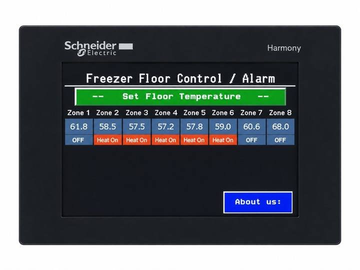
| Zone temperature | Current floor temperature (°F). With multiple sensors in a zone, the lowest reading is shown. |
| OFF | The floor is at or above setpoint; heat is off. |
| Heat On | The zone is below setpoint; the heating cable is energized. |
| ALARM | The floor is below the zone's low-temperature alarm point. |
| Set Floor Temperature | Press and hold for 3 seconds to open the Temperature Setpoint screen. |
| About us | Contact information, panel number, and access to troubleshooting and Fault History. |
Each zone controls to its own setpoint with a 2 °F differential to prevent short cycling.
Alarm conditions
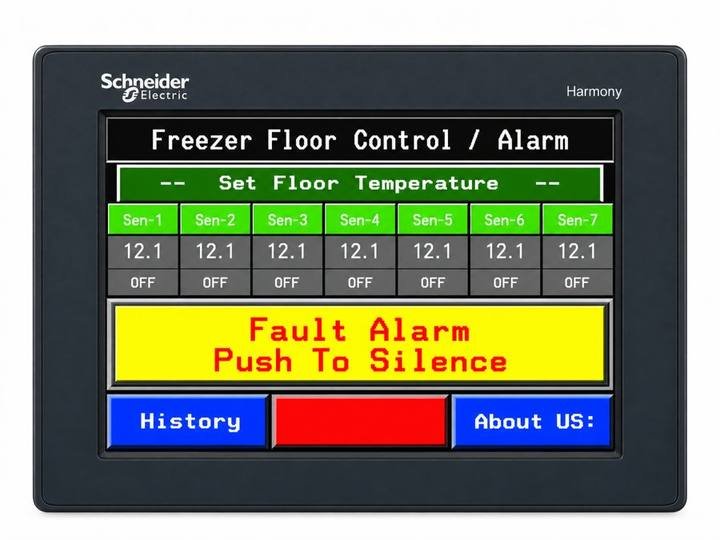
When a fault occurs (after a 5-second delay for temperature and monitor alarms):
- The horn sounds and the Fault Alarm – Push To Silence banner appears.
- The remote alarm signal (24 VDC) turns on.
- A yellow alarm button appears for each type of fault present: TEMP ALARM, GFI ALARM, CB ALARM or MONITOR ALARM. Press a button to open its detail screen. The buttons are hidden when there is no alarm.
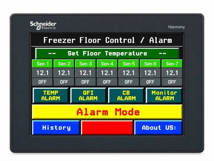
Silencing: press the banner (or any Silence button). The horn stops, the stack light turns on, and the Circuits in Alarm indicator turns yellow.
- If the fault is still present after 24 hours, the horn sounds again as a reminder.
- The remote alarm signal stays on as long as any fault exists, even when silenced.
- When all faults clear, the horn, stack light and alarm indicators reset automatically.
Sensor failure: if a thermocouple fails, a sensor alarm appears and that zone switches to timed operation, cycling heat on and off every 60 seconds until the sensor is repaired.
Power outage: active alarms reset when power is lost. If a fault still exists when power returns, it will alarm again.
Temperature setpoint
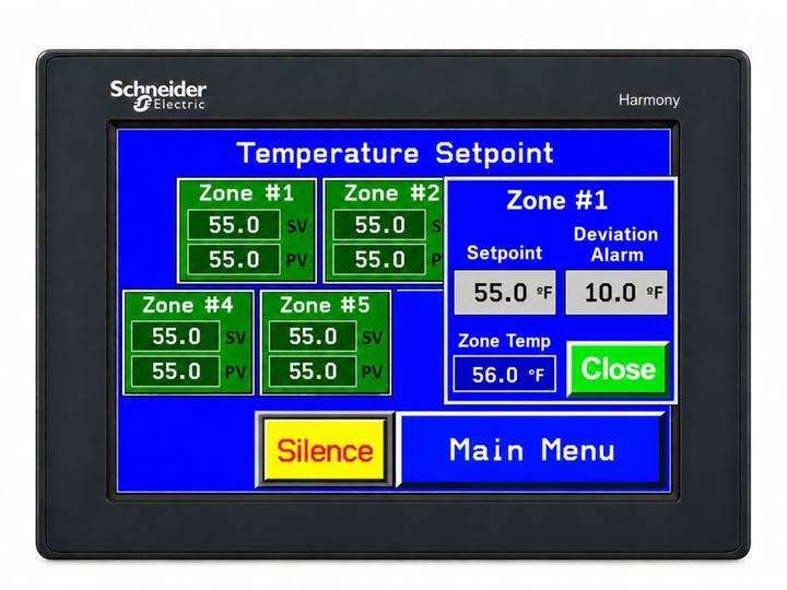
Open by pressing and holding Set Floor Temperature on the Main screen for 3 seconds. Each zone box shows SV (Set Value – the temperature the zone holds) and PV (Process Variable – the current floor temperature). Box colors: light green = normal, heat off; green = heat on; red = temperature alarm.
To change a zone: touch the zone box to open the setup window, touch Setpoint or Deviation Alarm, enter the new value, and press Close.
| Setting | Description |
|---|---|
| Setpoint | Floor temperature to hold. Range 32.0–100.0 °F. Normal setting 55.0 °F. |
| Deviation Alarm | How far below setpoint the floor may fall before a temperature alarm. Normal setting 10.0 °F (55.0 °F setpoint = 45.0 °F alarm point). |
| Zone Temp | Current floor temperature (display only). |
Temperature history (temperature alarm)
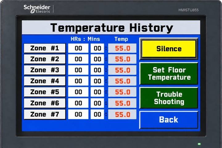
Open with the yellow TEMP ALARM button. HRs : Mins is the total time each zone has spent below its alarm point (accumulated until reset); Temp is the current floor temperature. A zone with long or repeated time in alarm should be checked.
Circuit monitor fault
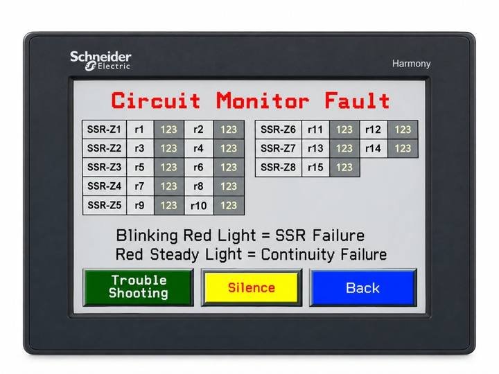
Open with the yellow MONITOR ALARM button. Each zone's solid-state relay (SSR-Z1, SSR-Z2 …) is listed with its end-of-run monitor relays (r1, r2 …) and their fault counts.
| Indicator | Meaning | Likely cause |
|---|---|---|
| SSR solid white | Normal | – |
| SSR blinking yellow | SSR failure – voltage on the circuit when the controller is not calling for heat | Shorted solid-state relay; replace the SSR |
| Relay (r#) steady yellow | Continuity failure – calling for heat but no voltage at the end of that run | Open heating cable, loose power or end connection, or failed monitor relay |
GFI monitor alarms
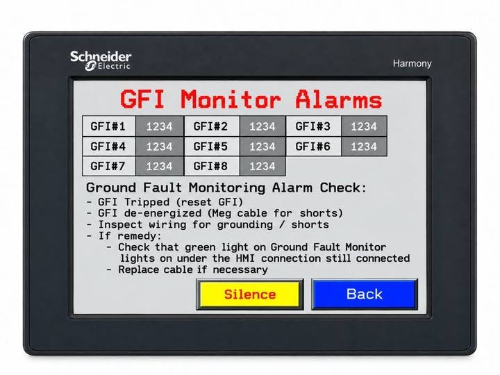
Open with the yellow GFI ALARM button. A GFI in alarm turns yellow. The alarm comes from an auxiliary contact on the breaker that signals when it is off or tripped.
- GFI tripped – reset the GFI.
- If the GFI will not stay on – de-energize and megger the cable for shorts.
- Inspect wiring and connections for grounding or shorts (moisture in junction boxes is a common cause).
- If the alarm continues, check that the green light on the ground fault monitor is lit and the HMI connection is still connected. Replace the cable if necessary.
Circuit breaker monitor

Open with the yellow CB ALARM button. A breaker in alarm turns yellow. Check for voltage on both sides of the breaker, check connections for shorts, and determine and fix the problem before resetting the breaker.
About Us

Shows the manufacturer's contact information and what to have ready when you call: company name, panel part number and serial number. Troubleshoot opens the Fault History screen.
Fault history
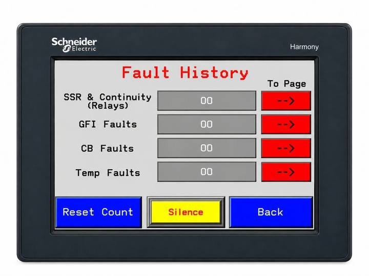
Open from About Us → Troubleshoot. Shows the number of SSR & continuity, GFI, CB and temperature faults since the last reset. Press the red arrow beside a fault type to open its detail screen. Reset Count – press and hold for 3 seconds to clear all fault counts and Temperature History times. Record the counts before resetting.
04Alarm summary
| Alarm | Cause | Screen indication | Action |
|---|---|---|---|
| Temperature | Floor below setpoint minus deviation (5-sec delay) | Zone ALARM / red; TEMP ALARM button | Check breaker, GFI, cable continuity and sensor. See Temperature History. |
| GFI | Ground fault breaker tripped or off | GFI ALARM; GFI turns yellow | Reset GFI; if it trips again, megger cable and inspect connections. |
| Circuit breaker | Breaker tripped or off | CB ALARM; CB turns yellow | Find and fix the cause before resetting. |
| Continuity | Calling for heat, no voltage at end of run (5-sec delay) | MONITOR ALARM; relay r# steady yellow | Check cable, power and end connections, monitor relay. |
| SSR failure | Voltage on circuit when not calling for heat | MONITOR ALARM; SSR blinking yellow | Replace the solid-state relay. |
| Sensor failure | Thermocouple open or disconnected | Sensor alarm | Zone cycles 60 s on / 60 s off. Check TC wiring; replace sensor. |
All alarms sound the horn and turn on the remote alarm signal. Silence stops the horn for 24 hours and turns on the stack light; the remote signal stays on until the fault clears.
05Maintenance
- Have a qualified electrician inspect the system yearly: megger each circuit, check amps and voltages, test each GFI, and test all alarms. Compare with the original startup checklist.
- Review and record the Fault History counts at each inspection.
- Keep junction boxes closed and conduit seals intact to keep out moisture.
- Never turn the system off while the freezer is in operation. The floor heat protects the slab from frost heave.