Sheet 02 · Design
System design
How an electric frost heave prevention system is built into the floor, how the conduit is laid out and how much heat it has to supply.
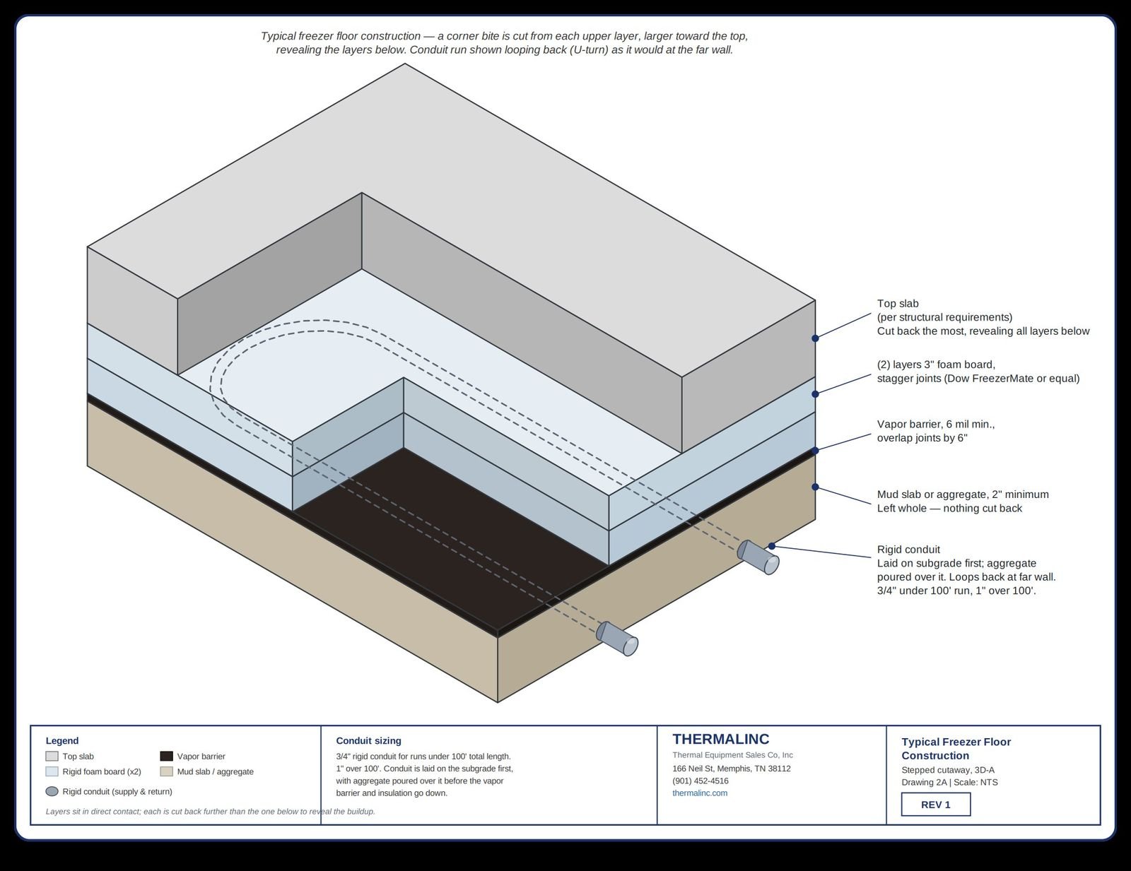
01Floor assembly
The heat goes into the base under the insulation, never into the slab. The room still pulls heat out of the floor, and the cable replaces it before the soil gives it up.
| Layer, top down | Typical |
|---|---|
| Wearing slab | Per structural design. |
| Insulation | Two layers of 3″ rigid foam board, joints staggered (Dow FreezerMate or equal). 4″ to 6″ total is common. |
| Vapor barrier | 6 mil minimum, joints lapped 6″. Keeps ground moisture out of the insulation. |
| Heated base | Mud slab or aggregate, 2″ minimum over the conduit, with at least 1″ between conduit and vapor barrier. Any non-insulating fill: rock, gravel, sand or lean concrete. |
| Heating conduit | Rigid conduit laid on the prepared subgrade first; base placed over it. |
| Subgrade | Prepared and compacted per the geotechnical report. |
02Conduit loops and junction boxes
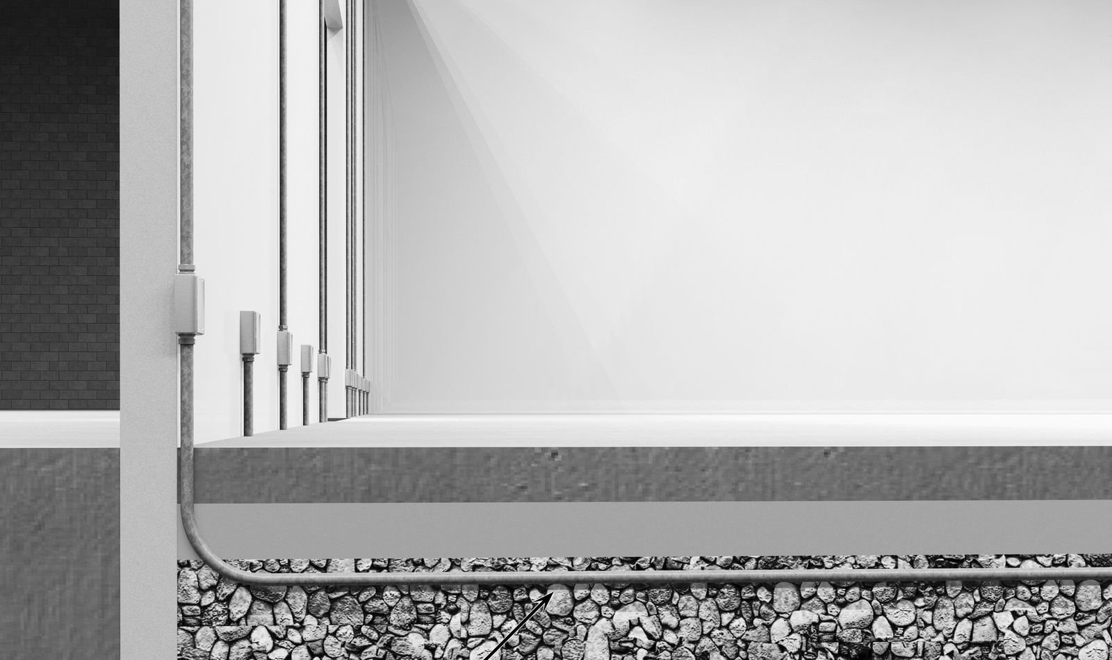
Each heating circuit runs in a hairpin loop: one continuous rigid conduit made of two parallel legs joined by a sweep near the far wall. Both ends turn up at the same wall. One end receives the power connection, the other the end-of-run connection, each in its own junction box.
- Size. ¾″ rigid conduit for loops under 100 ft total length; 1″ for loops over 100 ft.
- Bends. The 180° sweep plus two 90° risers total 360°, the most allowed between pull points for rigid conduit (NEC 344.26). Use large-radius sweeps so the cable pulls easily.
- No splices in the conduit. Each loop holds one continuous cable, terminated only in the junction boxes.
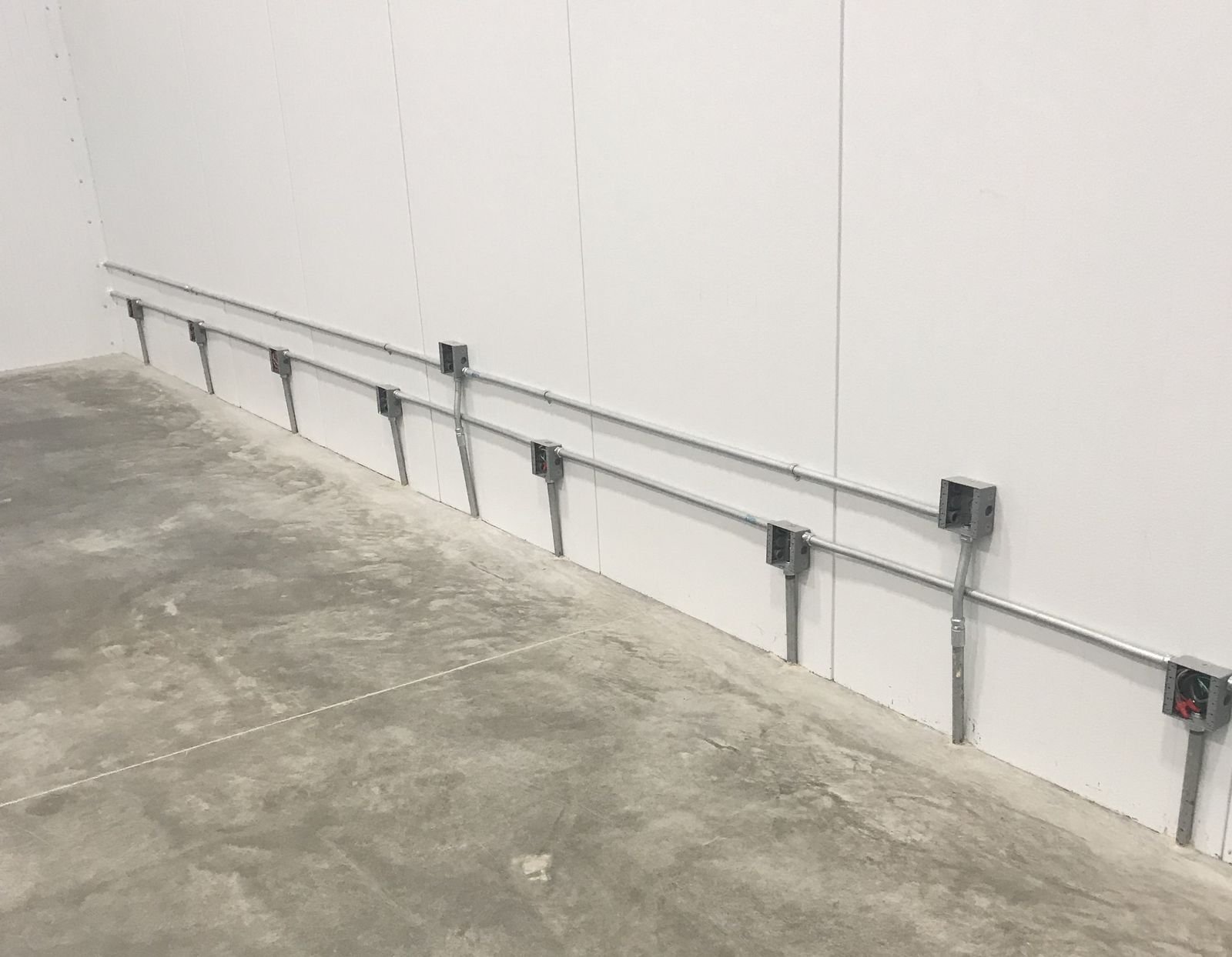
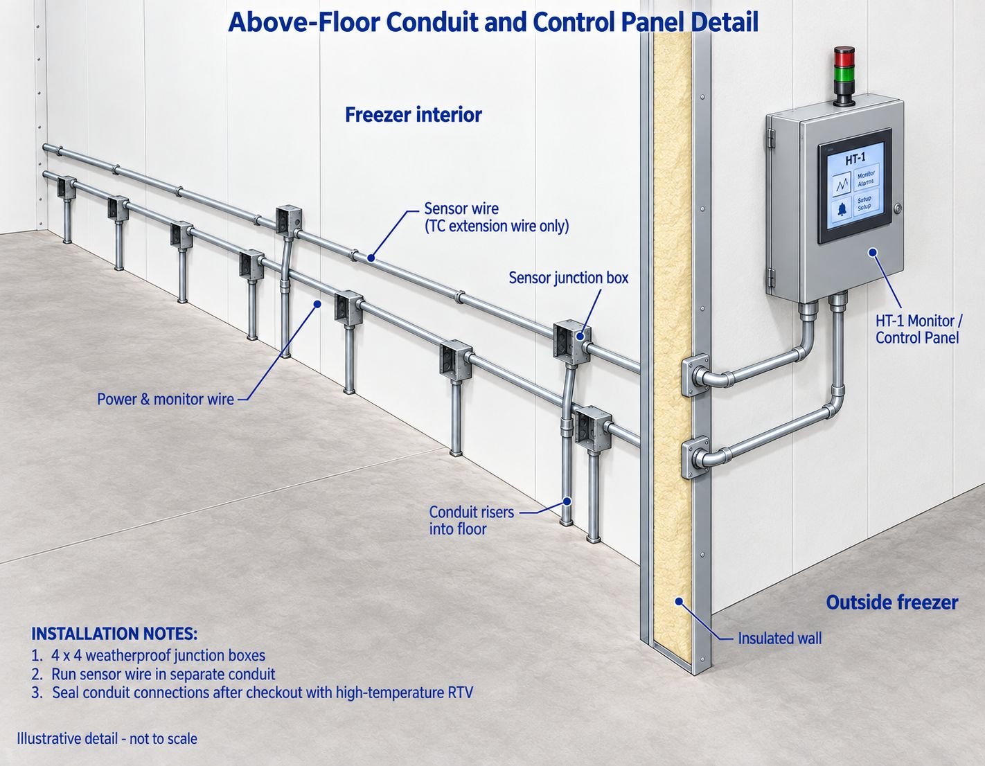
- Junction boxes. Weatherproof metal, 4″ square minimum, screw cover, accessible for testing, on the wall inside or outside the freezer.
- Sealing. After checkout, seal the conduit entries with high-temperature silicone to keep moist air from condensing and freezing in the conduit.
- Separate wiring. Run thermocouple extension wire in its own conduit, away from power wiring.
Because the cable is pulled in after the floor is poured, it is protected during construction and can be replaced later from the junction boxes.
03Layout rule
We lay out the legs evenly across the floor width with a strip of floor at each side wall. The numbers are whole inches and must satisfy
Width = A + (N − 1) × S + B
- N
- Number of conduit legs. Always even, since each loop has two. Use the smallest even N that works.
- S
- Leg spacing, center to center: 36″ to 48″, as close to 48″ as possible.
- A, B
- First and last leg from each side wall: each 12″ to 25″, split as evenly as possible.
| Width | N | S | A / B | Loops |
|---|---|---|---|---|
| 46′ (552″) | 12 | 48″ | 12″ / 12″ | 6 |
| 58′ (696″) | 16 | 44″ | 18″ / 18″ | 8 |
Loop ends stop about 18″ short of the far wall. Before routing conduit, check door openings, dock pits, column footings, drains and anything that will be anchored or cut into the floor.
Representatives can run this layout, with circuit zoning, in the rep layout calculator.
04Temperature sensors
- Type J thermocouple in its own ¾″ rigid conduit, capped at the far end, one per control zone.
- Place the sensor midway between two heating legs and toward the center of the heated area, where the ground runs coldest.
- Sensor lead length about half the floor width. Stainless overbraid with a fluoropolymer jacket for wet locations.
- Extend to the panel with Type J extension-grade wire (20 AWG, PVC/PVC). Make splices with silver solder; wire nuts are not acceptable on thermocouple wire.
05Heat cable
| Self-regulating (standard) | Constant wattage / MI | |
|---|---|---|
| Output | Polymer core; output rises as the cable gets colder and falls as it warms, all along its length. | Fixed output per foot; relies on the controller for all regulation. |
| Construction | 16 AWG bus wires, tinned copper braid, fluoropolymer or TPE overjacket. Maximum maintain temperature 150 °F. | Mineral-insulated (MI) cable has a metal sheath and a long service life, often cited at 25 to 50 years. |
| Installation | Flexible and easy to pull through conduit. | Stiff and harder to pull. Factory-made lengths. |
| Circuit length | Limited by start-up current. Calculate the maximum circuit length at a 32 °F start and size breakers for inrush. | Set by the cable design resistance. |
| In conduit | Output must be derated in metallic conduit. Low-temperature products are commonly derated about 40 %; use the manufacturer's value. | Watch sheath temperature in non-metallic conduit. |
Do not put high-temperature self-regulating or constant-wattage cable in non-metallic conduit unless the sheath temperature is checked against the conduit rating.
06Heat load
The required cable output depends on the freezer temperature, the insulation between slab and base, and the cable spacing. The table gives the required output in watts per foot of cable. Multiply by the cable length in the floor for the design load.
| Freezer | 2 ft | 3 ft | 4 ft |
|---|---|---|---|
| −40 °F | 6.4 | 7.3 | 9.1 |
| −20 °F | 4.1 | 5.1 | 7.0 |
| −10 °F | 3.6 | 4.3 | 5.5 |
| 0 °F | 3.2 | 4.0 | 4.8 |
| +10 °F | 2.7 | 3.0 | 3.4 |
| Freezer | 2 ft | 3 ft | 4 ft |
|---|---|---|---|
| −40 °F | 3.9 | 5.2 | 7.0 |
| −20 °F | 3.2 | 3.7 | 4.9 |
| −10 °F | 2.7 | 3.0 | 4.0 |
| 0 °F | 2.3 | 2.7 | 3.2 |
| +10 °F | 1.8 | 2.1 | 2.4 |
Example
A 58′ × 60′ freezer at 0 °F with 6″ insulation. The layout rule gives 16 legs at 44″ (3.67 ft). Interpolating the 6″ table at 0 °F: 2.7 + (3.2 − 2.7) × 0.67 ≈ 3.03 W/ft. Each leg is about 58.5 ft of heated length, so 16 legs plus the 8 sweeps come to about 980 ft of cable in the floor and roughly 3.0 kW of design load, about 0.86 W/ft².
Select a cable whose rated output at the base temperature, after conduit derating, is at least the table value. For elevated floors and slab edges exposed to outside air, add perimeter insulation and review edge losses separately.
07Codes and standards
- IEEE Std 515.1, testing, design, installation and maintenance of electrical resistance heat tracing for commercial applications
- NFPA 70 (National Electrical Code), Articles 426 and 427, including ground-fault protection of equipment for heating cable circuits
- NEC Article 344, rigid metal conduit
- Cable manufacturer's installation instructions and local codes