Sheet 06 · Project support
Project support
Every floor is laid out from its own dimensions, temperatures and electrical service. Send the basics and we return a layout and the details your electrician needs.
01What to send
- Floor plan with dimensions, door openings, dock pits, columns and drains
- Room design temperature, and any areas held at different temperatures
- Slab, insulation and base construction, or the architectural section
- Available electrical service: voltage and phase
- Preferred control panel location and distance to the floor
- For existing floors: age, history, any heave or temperature readings
Tip
Floor dimensions and room temperature are enough to start. Your local representative can run a preliminary layout with you.
02What we provide
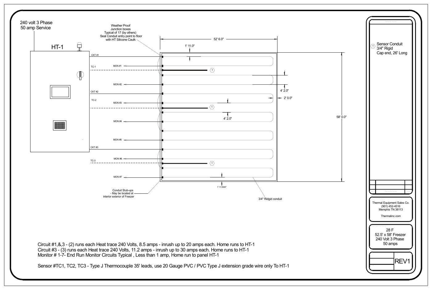
- Floor layout drawing with conduit locations, spacing and dimensions
- Electrical details: circuits, cable runs per circuit, running and inrush current, service required
- Control and monitoring wiring details, with wire types and maximum lengths
- Control panel schematic with terminal details
- Installation and startup instructions and a detailed checkout form
- Replacement parts list with standard, off-the-shelf part numbers
- Phone support during installation, startup and troubleshooting
03Installation sequence
- ConduitPrepare the subgrade. Set the conduit loops and capped sensor conduits per the layout. Cap all open ends.
- Base and floorPlace the aggregate or mud slab, then the vapor barrier, insulation and slab. Protect risers during the pour.
- Boxes and cableMount the junction boxes. Pull cable through each loop. Install power connection and end seal kits. Install sensors.
- Wiring and checkoutWire power, monitor and sensor circuits to the panel. Perform the checkout below. Seal conduit entries.
04Startup checkout
When the cable and connections for a circuit are complete:
- Inspect the cable. If it is damaged, replace the full length; no splices are made inside conduit.
- Check each connection kit: correctly assembled, moisture seal in place at every cable entry, caps installed.
- Test insulation resistance at the power connection with a 500 VDC megohmmeter (or the voltage the cable manufacturer specifies). Remove any cable reading less than 10 MΩ.
- Energize and record voltage at the end of each circuit. Confirm each end-of-run relay operates.
- Record the current on each cable at startup and again after 30 minutes. Keep these values for preventive maintenance.
- Test every alarm: low temperature, sensor break, ground fault, circuit fault, horn, beacon and remote contacts. Record the results on the checkout form.
Repeat the insulation resistance and current readings during periodic maintenance and compare them with the startup record.