Sheet 04 · Controls
Controls and monitoring
A frost heave system can fail quietly. The ground cools slowly, and by the time the floor moves the soil may be frozen deep. The controls have to find a failed circuit in hours, not after a season.
01What the controls must catch
Older heat cable controls watched current draw. That works for constant-wattage cable, where a healthy circuit draws a known current. Self-regulating cable draws different current as its temperature changes, so current alone cannot tell a healthy circuit from a damaged one.
Our panels confirm operation directly at the far end of each run and back it up with ground temperature:
- Far-end voltage, per circuit. Voltage present at the far end when the PLC calls for heat confirms the solid-state relay, breaker and cable are all passing power. Voltage present when the PLC is not calling for heat means a relay has failed shorted.
- End-of-run relay, per loop. A small relay at the end of each cable run proves continuity of that individual run.
- Ground-fault and breaker status, per circuit. Auxiliary contacts on each breaker report a trip.
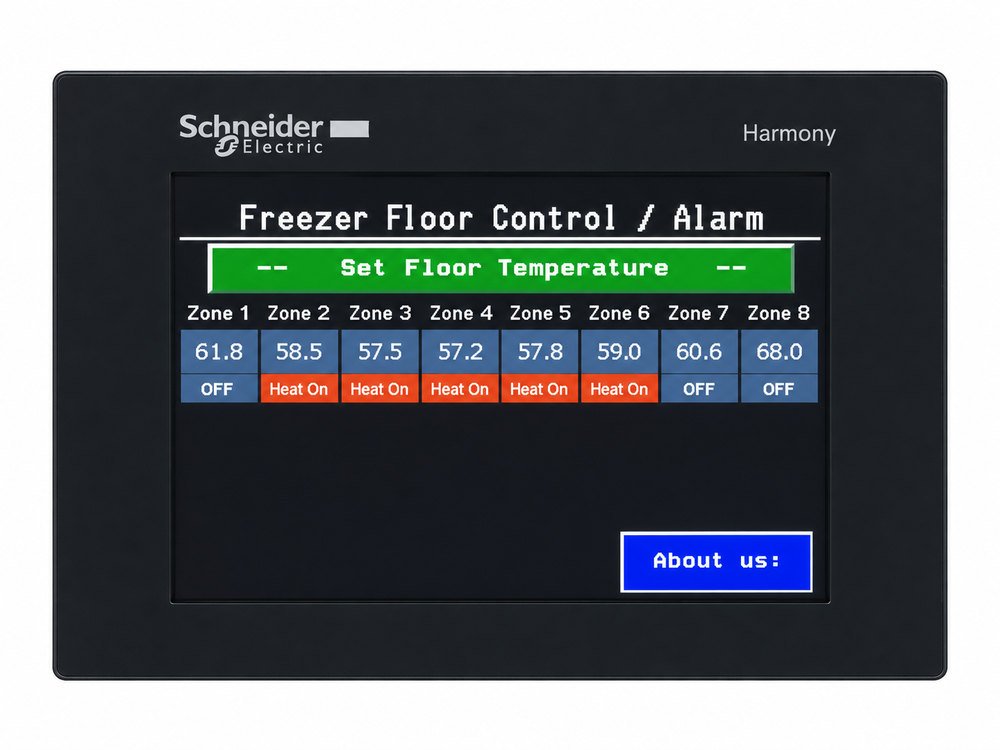
- Ground temperature, per zone. An independent check that does not rely on any electrical reading, with a low-temperature alarm and a thermocouple break alarm.
02System architecture
03Monitored points
| Point | Detects | Operator sees |
|---|---|---|
| Ground temperature | Zone below setpoint or below the low alarm limit | Zone temperature, heat on/off, low-temperature alarm and total time spent in alarm |
| Thermocouple circuit | Open or broken sensor lead | Sensor fault alarm with zone |
| Far-end voltage | Relay failed open, breaker off, cable open; relay failed shorted | Circuit fault with circuit number |
| End-of-run relay | Loss of continuity on an individual run | Run fault with location |
| Ground-fault breaker | Ground-fault or overcurrent trip | Breaker fault with circuit number |
| Fault history | Every event, with count per condition | Log with location, time in fault, troubleshooting steps and replacement part numbers |
04Alarms and remote monitoring
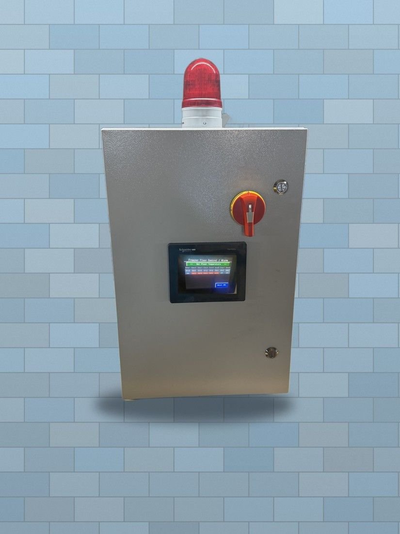
- 98 dB horn and flashing red beacon on any fault.
- Silencing the horn does not clear the alarm. The beacon stays on until the fault is corrected, and the horn re-sounds at a programmed interval until then.
- Dry alarm contacts or a 24 VDC output for a building management or plant control system.
- Ethernet with Modbus available for remote monitoring.
- Built-in troubleshooting guides on the touchscreen, tied to each fault.
05Temperature control
A PLC with thermocouple inputs holds each zone at a user-set temperature, which cannot be set below 32 °F. Each circuit is switched by a solid-state relay rated for heat cable inrush. Self-regulating cable already reduces its own output as the base warms; the controller switches it off entirely when the zone is at setpoint, which saves energy and reduces cable temperature cycling.
Peak setback. A remote 24 VDC input lowers the setpoint during utility peak-demand periods. The ground has enough thermal mass that a few hours of reduced heat do not affect it.
06Electrical protection
| Main disconnect | Door-interlocked, lockable for lockout/tagout |
|---|---|
| Branch protection | Dedicated breaker for each circuit, C-curve or otherwise rated for self-regulating cable inrush |
| Ground-fault protection | 30 mA ground-fault equipment protection on every heating circuit, with auxiliary contact to the PLC |
| Control power | Control transformer with fused primary and secondary; 24 V DC supply |
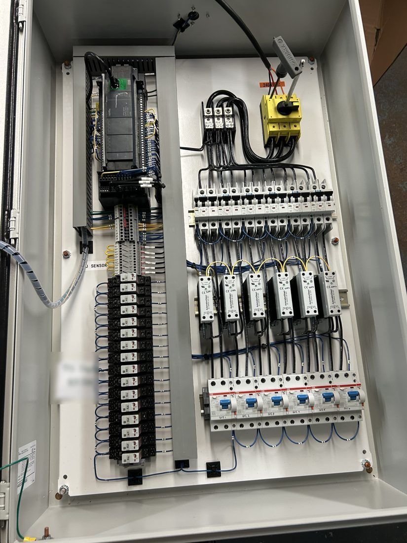
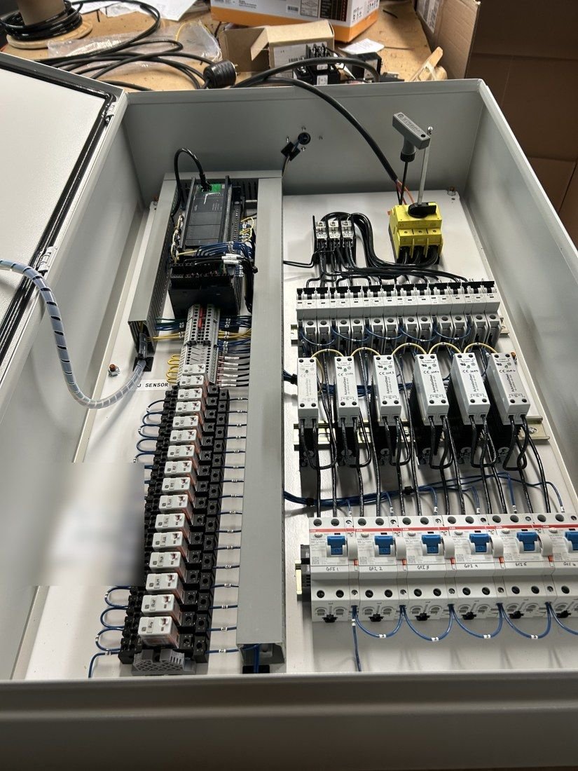
| Wiring | Pre-wired and tested at our shop; all field connections on labeled terminal strips; main lugs for incoming power |
07Enclosures and panel photos
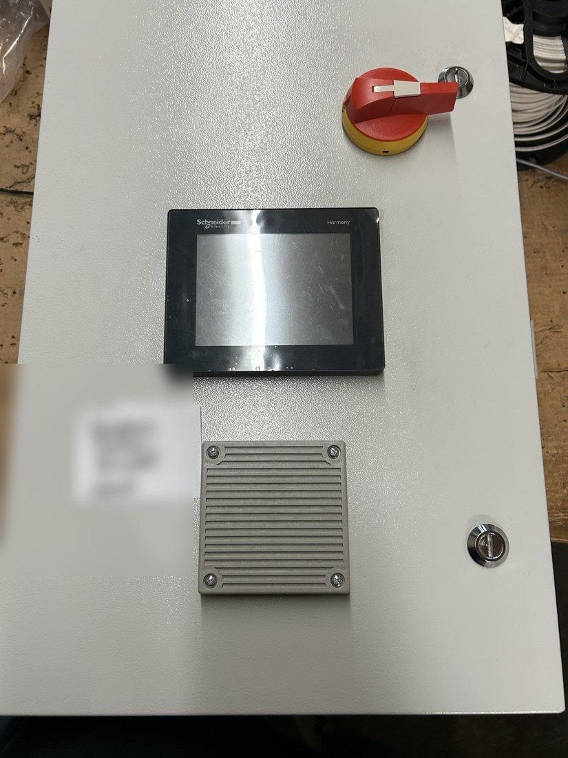
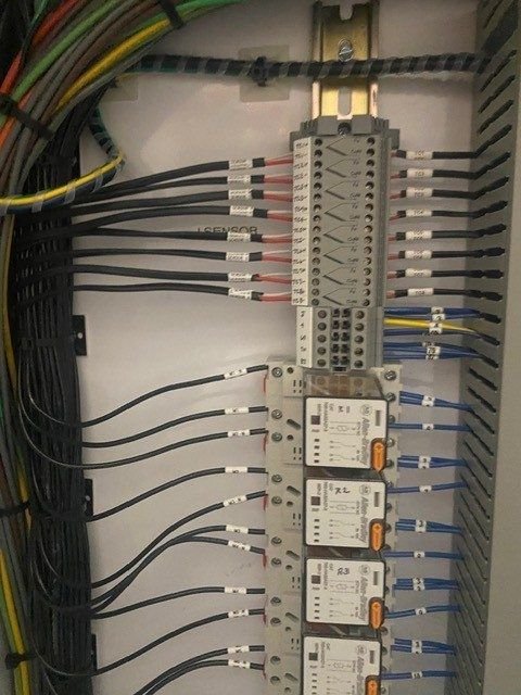
Panels are built in NEMA 12, 3R, 4 or 4X enclosures to suit the location, including NEMA 4X fiberglass and NEMA 4X stainless steel for food processing and washdown areas. Standard panels handle up to 5 circuits and 15 cable runs; larger panels have been built for up to 36 circuits and 72 runs.